Menu
REACTIVE POWER COMPENSATION
Reactive power compensation - theory and practice or how to eliminate reactive power fees.
Technical aspects
Most active current consumers draw active and reactive power from power grids or other supply sources. Active power is converted to useful energy and waste heat. Whereas reactive power, although it fails to conduct any work, is necessary for the correct operation of a number of electricity consumers (e.g., motors and transformers). Reactive power Q (VAr) is a measure of energy alternating between the inductive /L/ and capacitive /C/ element of a consumer, and an electricity source. This power significantly burdens the electricity source, leading to additional heat losses.
Reactive power equals the products of RMS of current and voltage, and the sine of the phase shift angle between voltage and current:
Single-phase consumers:
Q = U I sinφ
Three-phase consumers:
Q = 3 Uf If sinφ
where:
Uf If – root mean squares of phase currents and voltages,
U I – root mean squares of forward currents and voltages.
The relationship between individual powers is shown in Fig. 1.
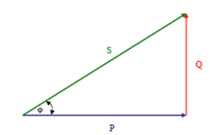
Where: P – active power [W]
Q – reactive power [VAr]
S – apparent power [VA] (geometric sum of active and reactive power)
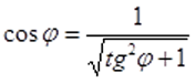
The measure for a reactive component of the current is the cosφ power factor, often also expressed as tgφ, specified in the technical terms for connection to a power grid, electricity tariff and other documents used in commercial power engineering. The specified tgφ power factor value can be converted into cosφ, using the formula:
Consumers operating at a low cosφ power factor value lead to increased operating current consumptions relative to operating with the same active power and power factor close to one.
A low power factor (cosφ) leads to a number of negative outcomes:
• the need to install generating and processing equipment with higher rated capacities,
• the need to use instrumentation with higher rated currents and higher permissible short-circuit currents,
• the need to use cables with larger cross-sections,
• reduced feeder grid capacity,
• increased active power losses in transformers, networks and consumer systems,
• increased voltage drops in feeder lines and transformers.
In customer electrical systems, where there are no inductive consumers, the cosφ power factor is close to one. Whereas in industrial and commercial facilities, its value can be significantly lower than one. This is mainly due to the installed process devices equipped with motors or other consumers with a low rated power factor.
An electric motor or transformer draws reactive power for magnetization almost equal to the apparent power at idle run and for covering reactive power losses under load.
Reactive power flow from the power source to the consumers leads to additional electricity consumption due to the losses. In order to mitigate these losses, the objective should be to limit electricity and reactive power consumption to values required for magnetization and covering losses under rated conditions.
The power of compensation equipment shall be calculated from the formula:
where:
P – consumer active power, in [kW]
k – (1.1 ÷1.3) correction factor resulting from system inertia
tgφn – natural power factor (no compensation)
tgφk – power factor required by the electricity provider.
The matched capacity of inductive reactive power compensation equipment shall not cause overcompensation that will manifest itself in a negative value of the cosφk power factor.
The verification shall be done using the formulas:
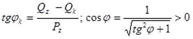
where:
Pz – active power demanded by consumers, in [kW]
Qz – reactive power demanded by consumers, in [kVAr]
Qk – capacity of devices for reactive power compensation in [kVAr].
A negative cosφ power factor value evidences overcompensation, which is harmful to consumers and the supply grid, resulting in increased voltage and higher harmonics (THD) at the compensator tie-in point.
Economic aspects
The technical aspects of the negative effects of reactive power flowing in a network have been discussed above. Exceeding permissible tgφ values entails also an additional financial burden.
According to the Regulation of the Minister of Economy of 4 May 2007 on the detailed functioning conditions of the electromagnetic system [Dz. U. of 2007, No. 89 item 623], the permissible consumption of reactive power from a power grid is determined by the tgφ index, the value of which shall not be higher than 0.4. At the same time, this Regulation enables the Distribution System Operator (DSO) to demand a value below 0.4 in justified cases (however, in practice, this value is never lower than 0.2).
Exceeding the permissible value of tgφ results in charging additional fees for the consumption of over-standard reactive power, which are specified in the electricity tariff approved by the president of ERO. In order to reduce inductive reactive power consumption from a power grid, it is compensated through the installation of compensation equipment that locally generates reactive power (e.g., capacitor banks).
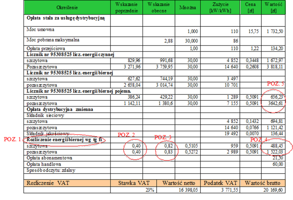
Below, based on an example of an electricity invoice (Table 1), we will analyse the items found in customers billed according to tariffs “B” and “C”. The conducted analysis will enable determining, which components are associated with reactive power and can be eliminated, thus reducing the monthly electricity bills.
The components of an electricity bill are [1] :
• distribution fee,
• subscription fee,
• grid fee,
• fee for exceeding contracted capacity,
• fee for reactive power (inductive as per tg φ),
• fee for added reactive power (capacitive).
While the subscription and grid fees cannot be eliminated, the fees for inductive and capacitive reactive power can.
As previously indicated, the measure for inductive reactive power consumption is the tgφ power factor (Tab1. No. 1) and it is used to settle reactive power fees. It indicates how much reactive power was consumed relative to the consumed active power. In our case, the tgφ required by DSO is 0.4 (Tab. 1 No. 2). The fee is charged when this value is exceeded, namely, when reactive power consumption relative to active power is higher than 40%. Devices that can lead to excessive reactive power consumption and associated fees are drive motors, ventilation systems, air-conditioners, lighting, lifts, etc. In the case in question, the true tgφ (the one actually achieved at the facility) is 0.83 (Tab. 1. No. 3), and is much higher than the 0.4 required by the DSO. A fee was charged in association with this overshoot. This item can be eliminated by installing compensation equipment with monthly savings of PLN 2 000 according to the sample invoice (Tab. 1. No. 4).
In the case of negative reactive power, the billing is based on the factor. Each smallest return of reactive power to the grid results in the fee being charged. Reactive power is returned due to the presence of a facility housing devices that are capacitors from the electrical perspective, such as UPSs, computers, LED lighting or extensive cable network. In the case in question, the amount due for negative reactive power (capacitive) is almost PLN 4 300 (Tab. 1. No. 5). By using relevant equipment for compensating capacitive reactive power, such as inductive reactors, this item can also be eliminated.
The conducted analyses that take into account the current price level of compensation equipment on our market (analysis conducted based on the OLMEX KMB capacitor bank price list) indicate that the return on investment for a reactive power compensation system is 4 to 12 months (depending on the capacity and grid parameters of a facility). However, this analysis did not cover facilities with dynamic loads (welders, overhead cranes) and with a high level of higher harmonics (THDI and THDU). The basis for the correct selection of a reactive power compensation system is an analysis (measurements) of electricity parameters at a facility, where the compensation system is to be installed. Such an analysis enables obtaining information on the rate and level of reactive power fluctuations, the presence of higher harmonics or load asymmetry. Based on that data, it is possible to design and construct a compensation system best fitted for the facility, which will fulfil its technical functions. We provide services in terms of measuring and selecting compensation equipment throughout the entire country.
[1] Not all bills have to contain every component. This depends on the electricity provider, billing tariff or consumption nature.